- +1 919 200-0292
- info@antennatestlab.com

Flipper Zero Antenna Patterns
Search results for:
Flipper Zero Antenna Patterns
We were curious about the viral Flipper-Zero device … just like everybody else is. It does have a sub-GHz radio and can record/playback modulated signals in the popular ISM bands of 315, 433, 868, and 915 MHz. The device’s documentation discloses that a “spring antenna” is used. Given that such a PCB mounted antenna is tiny compared to the transmit wavelength of about 1 meter (@315 MHz), the expected radiation efficiency would be quite small. This is a common compromise for handheld wireless devices … they normally do not use full sized antennas (1/2 wavelength or larger).
But how do you pattern test an antenna that is embedded into a device and connected to a live transmitter, when you don’t have access to the antenna RF port? We simply pattern the live tranmsitter in the anechoic chamber. The Flipper Zero was mounted on an all dielectric (plastic) 2-axis positioner and moved through hundreds of orientations while the far field radiated signal level was measured. The power units of dBm (logarithmic milli-Watts) are standard, and the phenomenon is called EIRP or Effective Isotropic Radiated Power.
If you spherically integrate the measured EIRP pattern, you get an average power which represents the device’s TRP or Total Radiated Power. This is a measure of the RF energy that has left the device and propagates outwards. Since we can lookup the Flipper’s CC1101 radio data-sheet conducted power, we can back calculate antenna efficiency, since the TRP is always less than the transmitter’s conducted output power. (Assuming the Flipper transmits at max power.)
The gallery below shows the measured 3D spherical EIRP patterns at the four main transmit frequencies, as well as the anechoic chamber test setup. The TRPs and efficiencies are summarized in this table.
| Frequency | TRP | TRP | CC1101 Max Pwr | Loss | Efficiency |
|---|---|---|---|---|---|
| 315.00 MHz | -10.1 dBm | 0.098 mW | +12 dBm | 22.1 dB | 0.62 % |
| 433.92 MHz | -18.9 dBm | 0.013 mW | +12 dBm | 30.9 dB | 0.08 % |
| 868.35 MHz | -10.7 dBm | 0.085 mW | +12 dBm | 22.7 dB | 0.54 % |
| 925.00 MHz | -9.7 dBm | 0.107 mW | +12 dBm | 21.7 dB | 0.68 % |
As you can see, small embedded antennas are very inefficient, however convenient. In all cases here, the antenna radiated less than 1% of the available RF power. Using a full sized high efficiency antenna has the potential to increase TRP by at least 20 dB, which is 100 times more power or about a 10x increase in communications range.


Amazon Tupavco TP542 13dBi WiFi Panel Antenna
A Directional WiFi Panel
We bought this popular antenna after becoming suspicious of it’s fairly high directivity (13 dBi gain) on both WiFi bands in the small 5″x9″ size and modest price. It turns out that it comes close to meeting these claimed specifications. It is about 10 dBi in the 2.4 GHz band and 14.5 dBi in the 5.5 GHz band. All reasonable for under $40. It was silicone sealed and would have some outdoor weather protection.
The photo gallery below has the pertinent performance graphs, measured 3D gain patterns, test setup photos, and internal views.


Consumer Antennas
More Fun Test Results
From time to time we test interesting consumer or surplus antennas just out of curiosity. This section of the website is a listing of their test results and our observations.
Amazon Tupavco TP542 Dual-Band (13dBi) Outdoor Directional Panel Antenna (2.4GHz & 5GHz WiFi)
Thermal Antenna Testing
Our Anechoic Thermal Chamber
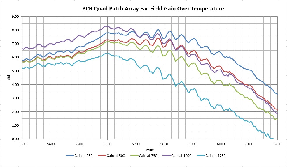
ATL is proud to be the first lab offering controlled temperature far field antenna testing. We can fully evaluate your antennas for gain/phase/efficiency patterns over the extended +25 to +125 degrees C range.
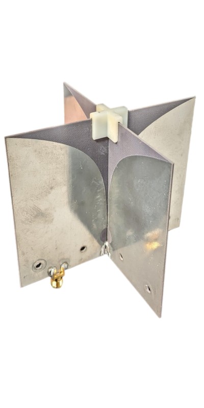
While we don’t heat the entire anechoic chamber, we have developed a thin film fluoropolymer Teflon high temperature envelope that’s only 0.002″ thick. Practically invisible to RF! Then using 1.5 kW of heated pressurized air to inflate the bag, we tightly PID control your antenna’s ambient air temperature. We even provide a detailed temperature log/graph recorded during your evaluation. This virtual anechoic thermal chamber allows many real-world effects to be studied, especially important on controlled permittivity/permeability substrates that can experience significant thermal degradation. For example, notice the considerable drop in gain for this simple PCB quad patch array antenna at 5.8 GHz. Its gain is degraded by 3 dB over temperature !
Now you can actually validate your antenna’s important parameters such as gain, efficiency, beamwidth, axial ratio, etc., over it’s full operating temperature range. No longer do you have to make due with just VSWR measurements in a thermal chamber and hope that far-field performance is in spec.


Example 15: Quad Ridge Dual Polarized Vivaldi Horn
This interesting eBay find is a Teflon PCB dual polarized Vivaldi pair. It was specified in its listing as 698 to 6000 MHz for mobile phone testing. With dimensions of 100x100mm, we suspected it was too small to work at 700 MHz, but the Teflon PCB material hinted at microwave performance.
We tested this antenna up to 18 GHz in full 3D gain at 669 frequencies. What we found was that the lower useable limit with any organized directivity was about 1500 MHz. Forward gain ranged from about +2 dBi to a maximum of +8 dBi over the useful spectrum up to about 10 GHz. Above that, the pattern fell apart and gain was highly variable. In fact, over the best operating range of 1.5 to 10 GHz, there was a lot of gain ripple making this a poor choice for calibration. The eBay seller branded this under “Sunflower Antenna”.
The Excel data set with graphs may be downloaded HERE
The 3D plot-files may be downloaded HERE


Eifagur 12dBi Panel Helium Antenna Review
Purchased for $99 from Amazon here on April 12, 2022
This antenna was given a full 3D spherical swept gain test program with gain measured in over 400 physical directions and at 200 frequencies. This kind of testing helps you visualize the full radiation sphere. With normal intended installation the antenna would be pointed in the Z axis in these diagrams with intended gain towards the horizon.
Marketed as a 12 dBi circularly polarized antenna, actual measured gain was as follows: 902 MHz +8.6 dBi; 915 MHz +8.5 dBi; 928 MHz 8.3 dBi.
As often is the case when marketed to consumers, this antenna falls short of the expected gain by 3.5 dB.
The antenna is indeed circularly polarized with RCHP gain being +8.0 dBic and LHCP of -1.5 dBic at 915 MHz. The axial ratio is poor, only 6.1 dB at 915 MHz broadside (Z Axis), degrading to 7.9 dB at 902 MHz. An axial ratio of 8 dB means the antenna would have an 8 dB change is response to slanted linear fields, where a good axial ratio would be close to 0 dB (truly circular and rotation independent). The images below are all click-to-enlarge.


Eifagur YCF-6927-10 10dBi Helium Antenna Review
Purchased for $45 from Amazon here on February 8, 2022
This antenna was given a full 3D spherical swept gain test program with gain measured in over 400 physical directions and at 200 frequencies. This kind of testing helps you visualize the full radiation sphere. With normal intended installation the antenna would be vertical (the Z axis in these diagrams) with intended gain towards the horizon (from the sides of the antenna) in the XY plane.
When marketed as a 10 dBi antenna, one would expect the gain in the “sideways” directions to be approximately 10 dBi. (This is way too good to be true – at a glace we can tell that this antenna is physically too small to possibly have omni-directional sideways gains of 10 dBi.) Actual measured sideways gain was as follows: 902 MHz -0.7 dBi; 915 MHz -1.1 dBi; 928 MHz -1.4 dBi.
While a peak gain of +2.6 dBi was measured, it was about 30 degrees above the horizon, and not really very useful. So this antenna is falling far short of the expected sideways gain/directivity by a whopping 11 dB. It is typical of consumer antennas to have over stated gains, so these results are not surprising. Although this is a fairly egregious over-statement of gain!
Upon disassembly, it can be seen that the antenna topology is a simple conical skirt monopole, which would normal have a sideways gain of 2 to 3 dBi. The 0.200″ diameter coaxial cable had a loss of 1.1 dB at 915 MHz.
The images below are all click-to-enlarge.


Bobcat 300 Helium Miner Antenna Review
Purchased along with a Bobcat Helium Miner
This antenna was given a full 3D spherical swept gain test program with gain measured in over 400 physical directions and at 200 frequencies. This kind of testing helps you visualize the full radiation sphere. With normal intended installation the antenna would be vertical (the Z axis in these diagrams) with intended gain towards the horizon (from the sides of the antenna) in the XY plane.
When specified as a 4 dBi antenna, one would expect the gain in the “sideways” directions to be approximately 4 dBi. Actual measured sideways gain was as follows: 902 MHz -0.5 dBi; 915 MHz +0.2 dBi; 928 MHz +0.4 dBi.
While a peak gain of +2.1 dBi was measured, it was about 30 degrees below the horizon, and not really very useful for “roof top” deployment. So this antenna is falling short of the promised sideways gain/directivity by 4 dB. It is typical of consumer antennas to have over stated gains, so these results are not surprising. Since this antenna has a side coaxial feed, it will not have the same radial symmetry as the bottom fed vertical antennas. The spherical average gain (averaged over the entire 3D sphere) was -1.3 dBi, indicating a quite respectable 74% radiation efficiency. Any 100% efficient antenna has a spherically averaged gain of 0 dBi maximum no matter how much gain/directivity is may have in some peak direction. The images below are all click-to-enlarge.


Bingfu 6dBi Helium Antenna Review
Purchased for $60 from Amazon here on February 8, 2022
This antenna was given a full 3D spherical swept gain test program with gain measured in over 400 physical directions and at 200 frequencies. This kind of testing helps you visualize the full radiation sphere. With normal intended installation the antenna would be vertical (the Z axis in these diagrams) with intended gain towards the horizon (from the sides of the antenna) in the XY plane.
When marketed as a 5.8 dBi antenna, one would expect the gain in the “sideways” directions to be approximately 5.8 dBi. Actual measured gain was as follows: 902 MHz -0.3 dBi; 915 MHz +0.9 dBi; 928 MHz +1.1 dBi.
While a peak gain of +4.1 dBi was measured, it was about 10 degrees below the horizon, and not really very useful. So this antenna is falling short of the expected sideways gain/directivity by about 5 dB. It is typical of consumer antennas to have over stated gains, so these results are not surprising. The images below are all click-to-enlarge.


Bingfu 3dBi Helium Antenna Review
Purchased for $40 from Amazon here on February 8, 2022
This antenna was given a full 3D spherical swept gain test program with gain measured in over 400 physical directions and at 200 frequencies. This kind of testing helps you visualize the full radiation sphere. With normal intended installation the antenna would be vertical (the Z axis in these diagrams) with intended gain towards the horizon (from the sides of the antenna) in the XY plane.
When marketed as a 3 dBi antenna, one would expect the gain in the “sideways” directions to be approximately 3 dBi. Actual measured gain was as follows: 902 MHz +0.2 dBi; 915 MHz +0.1 dBi; 928 MHz -0.1 dBi.
While a peak gain of +2.3 dBi was measured, it was about 10 degrees above the horizon, and not really very useful. So this antenna is falling short of the expected sideways gain/directivity by 3 dB. It is typical of consumer antennas to have over stated gains, so these results are not surprising. The images below are all click-to-enlarge.


